Exercises:Mond - Topology - 2
This is based on File:MondTop2016ex2.pdf and I hope to submit a PDF version for the assignment.
- This was difficult to do because of the number of pictures and MediaWiki's dire support for formatting them. The number of pictures also makes an email attachment containing large versions impractical, as such the link to this page is: https://wiki.unifiedmathematics.com/index.php?title=Exercises:Mond_-_Topology_-_2 and a "permanent link" here: https://wiki.unifiedmathematics.com/index.php?title=Exercises:Mond_-_Topology_-_2&oldid=3348 If a thumbnail isn't clear in the PDF please follow along on this page and click the image. The permanent-link version doesn't have this notice!
Contents
Section A
Section B
Question 5
Is the quotient map from [ilmath][0,1]\times[0,1]\subset\mathbb{R}^2[/ilmath] to the real projective plane, [ilmath]\mathbb{RP}^2[/ilmath], an open map?
Solution
We will consider the square as [ilmath]I^2\subset\mathbb{R}^2[/ilmath] where [ilmath]I:=[0,1]:=\{x\in\mathbb{R}\ \vert\ 0\le x\le 1\}\subset\mathbb{R}[/ilmath] with [ilmath]v_0=(0,0)[/ilmath], [ilmath]v_1=(1,0)[/ilmath], [ilmath]v_2=(0,1)[/ilmath] and [ilmath]v_3=(1,1)[/ilmath].
Definitions

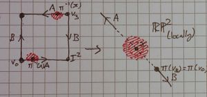
Notice that the diagonal which shows the image of the edges under [ilmath]\pi[/ilmath] is not straight or even smooth (shown at the extremes from [ilmath]\pi(v_3)[/ilmath]), we draw it this way for convenience!
- Let [ilmath]\pi:I^2\rightarrow\mathbb{RP}^2[/ilmath] be the quotient map the question talks about.
- Let [ilmath]\epsilon\in (0,\frac{\sqrt{2} }{2})\subset\mathbb{R} [/ilmath] be given, the upper bound is chosen so the open ball considered at a vertex does not cross any diagonals of the square.
- Let [ilmath]X:=B_\epsilon(v_3)\cap I^2[/ilmath], where the open ball [ilmath]B_\epsilon(v_3)[/ilmath] of radius [ilmath]\epsilon[/ilmath] centred at [ilmath]v_3[/ilmath] is considered in [ilmath]\mathbb{R}^2[/ilmath], thus [ilmath]B_\epsilon(v_3)\cap I_2[/ilmath] is open in the subspace topology [ilmath]I^2[/ilmath] inherits from [ilmath]\mathbb{R}^2[/ilmath]
Outline of solution
We will show that [ilmath]\pi[/ilmath] is not an open map, by showing that [ilmath]\pi(X)[/ilmath] has a boundary point, namely [ilmath]\pi(v_3)[/ilmath] itself and combine this with:
As [ilmath]\pi(X)[/ilmath] has a boundary point contained in [ilmath]\pi(X)[/ilmath] it cannot be open! We have exhibited an open set of [ilmath]I^2[/ilmath] (namely [ilmath]X[/ilmath]) which is mapped to a non-open set (namely [ilmath]\pi(X)[/ilmath]), thus [ilmath]\pi[/ilmath] cannot be an open map
Solution body
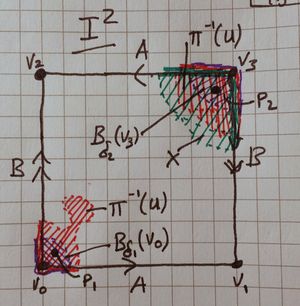
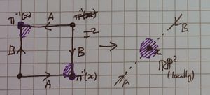
Notice that for any of the purple open balls, there is always a point ([ilmath]p_1[/ilmath] and [ilmath]p_2[/ilmath]) that is not a vertex point nor an edge point. This is key.
- Let [ilmath]\epsilon>0[/ilmath] be given such that [ilmath]\epsilon\in\mathbb{R} [/ilmath] and [ilmath]\epsilon<\frac{\sqrt{2} }{2} [/ilmath]
- Define [ilmath]X:=B_\epsilon(v_3;\mathbb{R}^2)\cap I^2[/ilmath] - the intersection of the open ball of radius [ilmath]\epsilon[/ilmath], in [ilmath]\mathbb{R}^2[/ilmath] and [ilmath]I^2[/ilmath], by definition of the subspace topology [ilmath]X[/ilmath] is open in [ilmath]I^2[/ilmath]
- We claim that [ilmath]\pi(v_3)\in\partial\pi(X)[/ilmath] - that is that [ilmath]\pi(v_3)[/ilmath] is a boundary point of [ilmath]\pi(X)[/ilmath].
- To show this we will use a point is in the boundary of a set if and only if every open neighbourhood to that point contains both a point in the set and a point not in the set
- Let [ilmath]U[/ilmath] be an arbitrary open neighbourhood in [ilmath]\mathbb{RP}^2[/ilmath] to [ilmath]\pi(v_3)[/ilmath] be given.
- As [ilmath]\pi[/ilmath] is continuous we have [ilmath]\pi^{-1}(U)[/ilmath] is open in [ilmath]I^2[/ilmath]
- As [ilmath]\pi(v_3)\in U[/ilmath] (by definition) and [ilmath]\pi(v_3)=\pi(v_0)[/ilmath] we see from [ilmath]\pi(v_0)\in U[/ilmath] that [ilmath]v_0\in\pi^{-1}(U)[/ilmath]
- As [ilmath]\pi^{-1}(U)[/ilmath] is an open set and [ilmath]v_0,v_3\in\pi^{-1}(U)[/ilmath] we see there exist [ilmath]\delta_1',\delta_2'>0[/ilmath] such that [ilmath]B_{\delta_1'}(v_0)\subset\pi^{-1}(U)[/ilmath] and [ilmath]B_{\delta_2'}(v_3)\subset\pi^{-1}(U)[/ilmath]
- Define [ilmath]\delta_1:=\text{Max}(\{\delta_1',\frac{\sqrt{2} }{2}\})[/ilmath] and [ilmath]\delta_1:=\text{Max}(\{\delta_1',\frac{\sqrt{2} }{2}\})[/ilmath] - this will prevent the following balls from crossing the diagonal of the square and keeps them disjoint.
- Notice the following: [ilmath]B_{\delta_1}(v_0)\subseteq B_{\delta_1'}(v_0)\subset \pi^{-1}(U)[/ilmath] and [ilmath]B_{\delta_2}(v_3)\subseteq B_{\delta_2'}(v_3)\subset \pi^{-1}(U)[/ilmath]
- Define [ilmath]p_1\in B_{\delta_1}(v_0)[/ilmath] to be any point in [ilmath]B_{\delta_1}(v_0)[/ilmath] such that [ilmath]p_1\ne v_0[/ilmath] and both the [ilmath]x[/ilmath] and [ilmath]y[/ilmath] coordinates are not [ilmath]0[/ilmath] (for example: [ilmath]p_1:=(\frac{\delta_1}{2},\frac{\delta_1}{2})[/ilmath] would do nicely)
- Define [ilmath]p_2\in B_{\delta_2}(v_3)[/ilmath] to be any point in [ilmath]B_{\delta_2}(v_3)[/ilmath] such that [ilmath]p_2\ne v_3[/ilmath] and both the [ilmath]x[/ilmath] and [ilmath]y[/ilmath] coordinates are not [ilmath]1[/ilmath] (for example: [ilmath]p_2:=(1-\frac{\delta_2}{2},1-\frac{\delta_2}{2})[/ilmath] would do nicely)Notice that [ilmath]\pi(p_2)[/ilmath] is inside the image of [ilmath]X[/ilmath] (green) and inside [ilmath]U[/ilmath], then contrast that with [ilmath]\pi(p_1)[/ilmath] which is not inside the image of [ilmath]X[/ilmath]. Purple shows the image of the open balls at each vertex, which we used to obtain [ilmath]p_1[/ilmath] and [ilmath]p_2[/ilmath]
- Notice: The situation is shown in the 3rd diagram on the right
- [ilmath]\pi(p_1)\in U[/ilmath] and [ilmath]\pi(p_2)\in U[/ilmath]
- [ilmath]\pi(p_2)\in\pi(X)[/ilmath]
- [ilmath]\pi(p_1)\notin\pi(X)[/ilmath]
- [ilmath]\pi(p_1)\neq \pi(v_3)[/ilmath] and
- [ilmath]\pi(p_2)\neq \pi(v_1)[/ilmath] It my be unnecessary to find a point distinct from the (suspected) boundary point inside and outside of [ilmath]X[/ilmath], however as it was only a minor detour, we have done it
- Note that [ilmath]\pi[/ilmath] restricted to [ilmath](0,1)\times(0,1)[/ilmath] (the interior of the [ilmath]I^2[/ilmath] considered in the space [ilmath]\mathbb{R}^2[/ilmath][Note 1]) is injective so we see [ilmath]\pi(p_1)\ne\pi(p_2)[/ilmath]
- Next, observe that (by design, this is the whole point of identification spaces like this) the edges by each point are mapped over each other (in direction depending on the arrows in the identification), as [ilmath]p_1[/ilmath] and [ilmath]p_2[/ilmath] are not on the edge, nor are they vertices, they are not mapped to it.
- So now we have: [ilmath]\pi(p_1)\in U[/ilmath], [ilmath]\pi(p_2)\in U[/ilmath] and importantly, for the boundary point theorem mentioned above:
- [ilmath]\pi(p_1)\notin\pi(X)[/ilmath] and [ilmath]\pi(p_2)\in\pi(X)[/ilmath]
- Notice: The situation is shown in the 3rd diagram on the right
- Since our choice of [ilmath]U[/ilmath] (an open neighbourhood to [ilmath]\pi(v_3)[/ilmath]) was arbitrary, we have shown for all such [ilmath]U[/ilmath] there exists points inside of [ilmath]U[/ilmath] such that 1 is inside [ilmath]\pi(X)[/ilmath] and one is outside [ilmath]\pi(X)[/ilmath]; namely [ilmath]\pi(p_1)[/ilmath] and [ilmath]\pi(p_2)[/ilmath].
- We actually went a bit to far and found a point in the interior of [ilmath]\pi(X)[/ilmath]
- Let [ilmath]U[/ilmath] be an arbitrary open neighbourhood in [ilmath]\mathbb{RP}^2[/ilmath] to [ilmath]\pi(v_3)[/ilmath] be given.
- We apply the theorem: "a point is in the boundary of a set if and only if every open neighbourhood to that point contains both a point in the set and a point not in the set" to show:
- [ilmath]\pi(v_3)\in\partial(\pi(X))[/ilmath] (where [ilmath]\partial A[/ilmath] denotes the boundary of a set [ilmath]A[/ilmath] in some topological space)
- Next, we recall the theorem: "a set is an open set if and only if it contains none of its boundary points"
- Well, [ilmath]\pi(v_3)\in\partial(\pi(X))[/ilmath] so [ilmath]\pi(X)[/ilmath] contains (at least) 1 of its boundary points, therefore it cannot be open.
- As [ilmath]X\subset I^2[/ilmath] is open, but its image, [ilmath]\pi(X)\subset\mathbb{RP}^2[/ilmath] is not open, [ilmath]\pi[/ilmath] cannot be an open map, as:
- To be an open map, the image of every open set in the domain ([ilmath]I^2[/ilmath]) must be open in [ilmath]\mathbb{RP}^2[/ilmath], we have demonstrated this is not the case
- Define [ilmath]X:=B_\epsilon(v_3;\mathbb{R}^2)\cap I^2[/ilmath] - the intersection of the open ball of radius [ilmath]\epsilon[/ilmath], in [ilmath]\mathbb{R}^2[/ilmath] and [ilmath]I^2[/ilmath], by definition of the subspace topology [ilmath]X[/ilmath] is open in [ilmath]I^2[/ilmath]
Thus [ilmath]\pi[/ilmath] is not an open map.
Question 6
The picture on the right shows that [ilmath]\mathbb{RP}^2[/ilmath] contains a Mobius strip, [ilmath]M[/ilmath]. Use the diagram, taking into account the glueings, to describe the complement of [ilmath]M[/ilmath] in [ilmath]\mathbb{RP}^2[/ilmath]. You mare allowed to cut it, provided you then glue it back together.Complete the following sentence in as clear a way as possible:
- "[ilmath]\mathbb{RP}^2[/ilmath] is obtained from a Mobius strip by ....."
Solution
I only claim to find a topological immersion - the result is not a homeomorphism as it isn't a bijection.

The steps are:
- Create the Mobius band and put it aside for the moment, call it [ilmath]M[/ilmath].
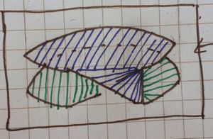
- Take a disk. Call it [ilmath]N[/ilmath]. This is shown in the picture on the right
- Stretch the disk slightly, the goal is to create something that resembles two disks joined, but not joined at a point. If you were to take a small "sausage" of blu-tac, and pinch the edges you'd end up with 2 disks joined by a strip of blu-tac, we want this. This is shown in the first 3 stages of the series on the right.
- Caution:We do not want, nor do we mean, two circles joined at a point (see: wedge product)
- We cut in the edges slightly, so we no longer have two disks, but rather cut in disk with a rectangle coming off it. This is hard to describe and shown in stage 4 in the series on the right
- We now (topologically) embed the resulting shape in [ilmath]\mathbb{R}^3[/ilmath] (rather than the plane, [ilmath]\mathbb{R}^2[/ilmath]) - shown in stage 5
- Looking at the "cut in" disk furtherest away from the observer in my drawing, we look at the line which (if drawn) would mark the disk's edge and the rectangle that connects the disks start. We take that line and we rotate it [ilmath]90^\circ[/ilmath] around the depth axis, so it is vertical, and perpendicular to the disks. We also raise the nearest-the-observer-disk by a height which is the height of the Mobius Band [ilmath]M[/ilmath]. This is shown in step 6.
- The "rectangle" joining the two is now distorted by a twist along it.
- We now start to move the upper disk over the lower disk, as we do so we rotate it to keep the distorted rectangle between them as in-alignment as we can. This is shown in step 7
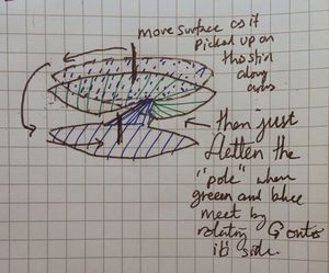
- Lastly, and by step 8 we have moved-and-rotated the upper disk over the lower. By preserving the rectangle as best we can there is automatically an "inner edge" that is shown passing behind and through into the "top" disk. Hopefully we have created the right hand side of the second picture:
- Blue represents the top disk
- Green represents the bottom disk
- Stretch the disk slightly, the goal is to create something that resembles two disks joined, but not joined at a point. If you were to take a small "sausage" of blu-tac, and pinch the edges you'd end up with 2 disks joined by a strip of blu-tac, we want this. This is shown in the first 3 stages of the series on the right.
- Position the result "inside" the cylinder that bounds the mobius strip
- Make any minor adjustments, so that the boundary of the band and the "double-disk-twisted-back-thing" we have made can be trivially stitched together, so trivially that the result is a union operation.
- It is now trivial to "stitch" the edges together. (As shown in the second picture on the right)
The workings below are more detailed and formal. I have not drawn a picture of [ilmath]\mathbb{RP}^2[/ilmath] immersed in this way for two reasons:
- The picture was extremely messy and not useful if I showed both disks and the "twist" of the rectangle between them
- The picture looked like a cylinder with a twist in the wall if I just drew the "top" of it and the Mobius band.
I hope it doesn't seem like a cop out to say:
- I actually really like my union drawing, it is surprisingly clear.
Solution workings
| Step | Picture | Comment |
|---|---|---|
| 1 Dividing up the square |
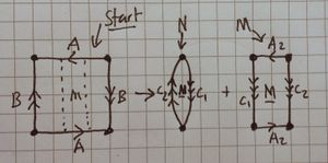
We first take the square and cut it up, creating new edges for gluing, [ilmath]C_1[/ilmath] and [ilmath]C_2[/ilmath] (see the picture at the top of this question) |
To yield two "chunks", [ilmath]N[/ilmath] and [ilmath]M[/ilmath]. |
| 2 Making the Mobius band |
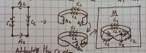
We start with [ilmath]M[/ilmath] on the left. | Pretty self explanatory and routine, my pictures turned out really well, I am a little bit proud. |
| 3 Joining the [ilmath]C_2[/ilmath] edges |
 we start off with the red, pulling the C2 edge between [ilmath]v_1[/ilmath] and [ilmath]v_2[/ilmath] part way around the [ilmath]C_2[/ilmath] edge of the band, then we let it return to [ilmath]v_1[/ilmath], [ilmath]v_1[/ilmath] and [ilmath]v_2[/ilmath] are added only for clarity. The next stage is purple, we stitch more of the edge along the [ilmath]C_2[/ilmath] edge of the band, then: Into blue, we pull it almost all the way round back to [ilmath]v_1[/ilmath]. |
The picture here shows only "half" of the [ilmath]N[/ilmath] surface, it is the result of stitching along the [ilmath]C_2[/ilmath] boundary.]] |
| 4 Joining the [ilmath]C_1[/ilmath] edge |
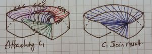
We start with the green and just pull the [ilmath]C_1[/ilmath] edge along and start stitching. Then we pull that around - and stitch along the way - resulting in purple. Then we pull that almost all the way around yielding red.
As before, we then pull the free-edge in, until there's a tiny gap and the remaining join results in almost parallel curves. The right hand image shows the result, which is significantly simpler than the [ilmath]C_2[/ilmath] case | |
| 5 [ilmath]N[/ilmath] surface |
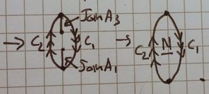
This shows what becomes of [ilmath]N[/ilmath] when it is stitched to [ilmath]M[/ilmath] along the [ilmath]C_1[/ilmath] and [ilmath]C_2[/ilmath] boundaries shown earlier, without [ilmath]M[/ilmath] drawn. | |
| 6 Final topological immersion |
A diagram showing them together is very cluttered and hard to see (it either looks a mess, or a cylinder with a twist in the side), so I will show it like this.
We see (a topological immersion) of [ilmath]\mathbb{RP}^2[/ilmath] in [ilmath]\mathbb{R}^3[/ilmath] is simply the union of a Möbius strip together with a "solid 8" shape, oo but joined. Take the left "disk" in this formation and lift it, then rotate it over the first disk in the formation. In this picture we imagine sticking a "stick" into the centre of the blue disk, on which the blue "wheel" can rotate freely, we move that stick along the arrows shown, the result is blue-and-green joined along a vertical pole. If you rotate that "pole" anticlockwise, so onto it's side, parallel to the x-axis on the paper it is drawn, you then have a [ilmath]oo[/ilmath] shape where the [ilmath]o[/ilmath]s are joined (that "pole" being the join between the two) | |
- Media:FullPageForRp2TopImmersion.JPG shows a picture of the entire page containing most of my drawings, these may help with marking.
Question 7
Both the Klein bottle and the real projective plane are [ilmath]2[/ilmath]-manifolds[Note 2]. This is not obvious from their descriptions as quotients of the square by an equivalence relation. In fact each point [ilmath]x[/ilmath] does have an open neighbourhood homeomorphic to an open set in [ilmath]\mathbb{R}^2[/ilmath]. Show by carefully labelled drawings that this is true if:
- [ilmath]x[/ilmath] is in the image of the interior of the square.
- Caution:Mond VERY PROBABLY ALMOST CERTAINLY means the interior of the square considered as a set in [ilmath]\mathbb{R}^2[/ilmath], as of course the square's interior is itself when considered as a topological subspace
- [ilmath]x[/ilmath] is in the image of an edge in the square, but not of a vertex.
- [ilmath]x[/ilmath] is the image of a vertex.
Your drawings for 2 and 3 have to make use of the fact that the edges of the square are glue together in passing to the quotient.
Solution
Definitions
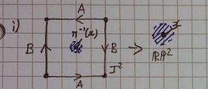
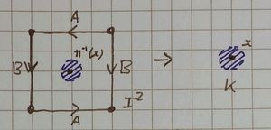
We take the following diagrams as the "square-edge-gluing" (identification?) diagrams used:
Solution body
Notice this is [ilmath]\mathbb{RP}^2[/ilmath] in the first column. Pictures have comments underneath.
- To see these in a table rather than as separate images see Media:TableSourceForLocallyKbottleAndRP2.JPG
The work here is done very informally. I emailed a link to: Media:RP2locallyDraft.JPG and was told this was the right idea.
| Type | [ilmath]\mathbb{RP}^2[/ilmath] | Klein bottle |
|---|---|---|
| Case [ilmath]1[/ilmath] | ||
| these cases are self explanatory and trivial, for any point in the interior of the square (considered in [ilmath]\mathbb{R}^2[/ilmath]) [ilmath]\pi[/ilmath] is injective (in fact [ilmath]\pi[/ilmath] restricted to the interior of the square (considered in [ilmath]\mathbb{R}^2[/ilmath]) is a homeomorphism onto its image), this can be used to show that given any such [ilmath]x[/ilmath] there is an open ball around [ilmath]x[/ilmath] which does not touch any edges or vertices of the square, or their images. | ||
| Case [ilmath]2[/ilmath] | ||
| The other cases are essentially the same just with the nearest vertex (marked here as [ilmath]\pi(v_0)=\pi(v_3)[/ilmath]) on the other side, or the arrows going another direction. | The other cases are just as in the already shown [ilmath]\mathbb{RP}^2[/ilmath] case, possibly with arrows in a different direction, or the nearest vertex on the other side. | |
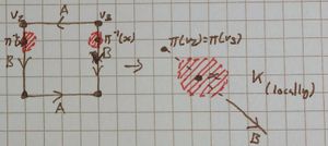
| To be explicit, notice the edges in the square have a red border where the red open sets are, this is to convey the edges are in that set. The passing to the quotient operation will map the edges onto each other, gluing the red set together along it, in the direction of the arrow on that edge.
What we are really showing here is an open ball in the chart, centred at [ilmath]x[/ilmath] and it's pre-image in the chart, then that's pre-image under the quotient map (in the square) This comment also applies to the third case. | ||
| Case [ilmath]3[/ilmath] | 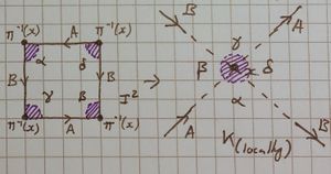 there's a slight mistake in this diagram, notice that all the other diagrams have a border around the exterior of the square to denote that they include that part of the edge, or that vertex, they should be present here. That is all the purple sections should include the edge they touch as well as the vertex. Please imagine them in. | |
| The other case is essentially the same just with the arrow directions reversed. | There is no other case. I have put [ilmath]\alpha,\beta,\gamma[/ilmath] and [ilmath]\delta[/ilmath] in each quadrant to show which shaded in bit belongs to which | |
Question 8
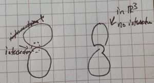
Here is a proof that the Klein bottle can be topologically embedded in [ilmath]\mathbb{R}^4[/ilmath]. The drawing on the right below shows the image of a failed embedding of the Klein bottle in [ilmath]\mathbb{R}^3[/ilmath], [ilmath]f:K\rightarrow\mathbb{R}^3[/ilmath]. The surface has to pass through itself in order for the two ends of the cylinder to glue together as required.
To embed [ilmath]K[/ilmath] in [ilmath]\mathbb{R}^4[/ilmath] the map [ilmath]f[/ilmath] needs one further component, [ilmath]f_4:K\rightarrow\mathbb{R} [/ilmath]. You can describe [ilmath]f_4[/ilmath] by specifying its value at each point of [ilmath]K[/ilmath]. By taking care that [ilmath]f_4[/ilmath] distinguishes points on [ilmath]K[/ilmath] which have the same image under [ilmath]f[/ilmath] in [ilmath]\mathbb{R}^3[/ilmath] (i.e. in the picture), you obtain an embedding. Copy the right hand picture and write suitable values of [ilmath]f_4[/ilmath] on your copy. Your [ilmath]f_4[/ilmath] should be continuous.
Solution
| The idea here is that I use a green line's thickness to denote the value of [ilmath]f_4[/ilmath], and assume it is 0 unless specified. In this image we associate the thinner "component" (I do not want to invoke a formal definition) of the bottle with the green line shown inside of it, and we show the bulb-like component with a line representing [ilmath]f_4=0[/ilmath]. The idea is we "lift" the smaller component over the bulb where they would otherwise intersect, then lower it back down afterwards. | I sense this is the kind of thing that you're after (Mond, my tutor, has drawn a diagram like this before). We assign 0 to everything, and as the thinner component comes to intersect the "bulb", we raise it, continuously, which I've tried to convey by first raising from [ilmath]0[/ilmath] to [ilmath]\frac{1}{2} [/ilmath] then [ilmath]1[/ilmath] then back down to [ilmath]\frac{1}{2} [/ilmath] then 0.
The blue line is intended to convey the bulb stays at [ilmath]f_4=0[/ilmath] |
Lower dimensional analogy
| I want to convey understanding. This is a very similar lower-dimensional analogy, we have the figure-8 / [ilmath]\infty[/ilmath] space, and we want to make it into an embedding in [ilmath]\mathbb{R}^3[/ilmath]. To do this we first take the [ilmath]\infty[/ilmath] flat into [ilmath]\mathbb{R}^3[/ilmath] then pick one of the components of the line (it doesn't matter which) and in a small area alter it's new coordinate so it goes "over" where it'd otherwise intersect. |
Section C
Notes
- ↑ As the interior of [ilmath]I^2[/ilmath] considered in the topological space [ilmath]I^2[/ilmath] is [ilmath]I^2[/ilmath] of course!
- ↑ Manifolds of the topological variety


